Building Smart Home Automation Systems with ESP32, DHT11, Light Sensor, and Blynk IoT
Jan 24, 2025Build a smart home automation system using ESP32, DHT11, light sensor, and Blynk IoT. Monitor temperature, humidity, light, and control devices remotely.
Building Smart Home Automation Systems with ESP32, DHT11, Light Sensor, and Blynk IoT
The ESP32, a versatile and powerful microcontroller, has become a cornerstone in the world of DIY smart home automation. This article explores how to create a comprehensive home automation system using the ESP32, a DHT11 temperature and humidity sensor, a light sensor, and the Blynk IoT platform. This combination allows for remote monitoring and control of various aspects of your home, enhancing convenience, comfort, and energy efficiency. We will delve into the components required, circuit diagrams, Blynk setup, and example code to get you started on your journey to a smarter home.
Understanding the Core Components
Before diving into the specifics of the build, let's understand the function of each key component:
-
ESP32 Microcontroller: The brain of our system, the ESP32 is a low-cost, low-power system-on-a-chip (SoC) that includes Wi-Fi and Bluetooth connectivity. It is responsible for processing sensor data, controlling actuators, and communicating with the Blynk IoT platform.
-
DHT11 Sensor: This sensor measures both temperature and humidity levels in its surrounding environment. It is a cost-effective option for basic environmental monitoring, although it provides only one measurement per second.
-
Light Dependent Resistor (LDR) / Light Sensor: An LDR, or light sensor, detects the intensity of ambient light. This data can be used to automate lighting or other light-sensitive devices.
-
Blynk IoT Platform: The Blynk platform provides a cloud-based service and mobile application that enables you to monitor your project's data and control its devices remotely. It allows for the creation of custom dashboards and provides a seamless user experience.
Setting up the Hardware
To build our ESP32 DHT11 light sensor Blynk IOT home automation system, we need to connect the components correctly. Here's a general outline of the connections. The connections may vary slightly based on your specific module.
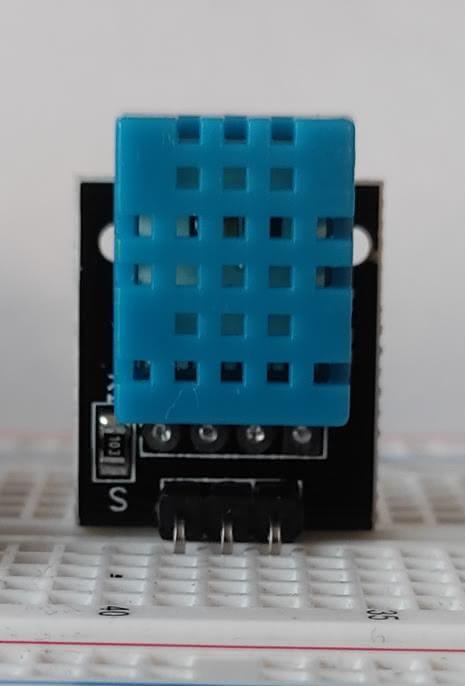
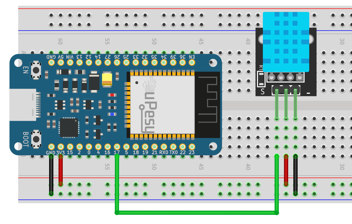
Connecting the DHT11 Sensor
The DHT11 sensor typically has three to four pins. If you have a 3 pin model, connect the VCC pin to the 3.3V output of the ESP32, the GND to ground, and the data pin to a GPIO pin of your choice (e.g., GPIO17). For a 4-pin module, one pin is typically not connected.
 Credit: www.upesy.com
Connecting the Light Sensor (LDR)
Connect the LDR in series with a resistor (typically 10kΩ) to create a voltage divider. Connect the junction between the LDR and the resistor to an analog input pin (e.g., VN) on the ESP32. Connect the other end of the resistor to ground, and the other end of the LDR to 3.3V.
Connecting Relays (For Appliance Control)
If you want to control appliances, you will need a relay module. Connect the relay's VCC and GND to the ESP32's 5V and GND. Connect the input pin (IN) of the relay to one of the ESP32's GPIO pins (e.g., GPIO 23). Remember to connect the AC appliances using proper safety precautions.
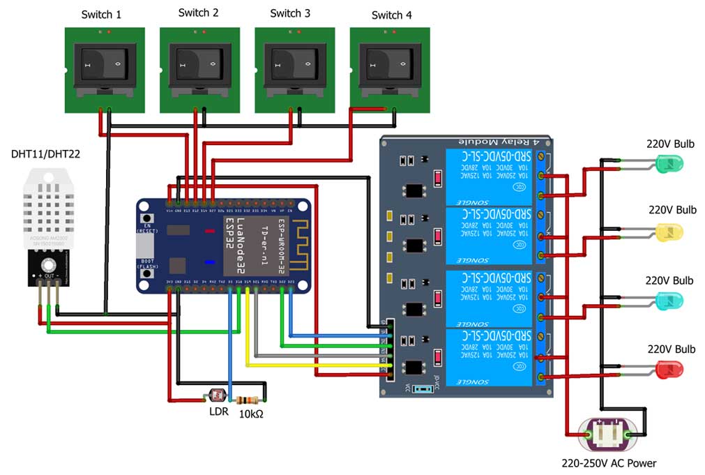
Complete Circuit Diagram
 Credit: www.upesy.com
 Credit: iotprojectsideas.com
These diagrams show examples using the ESP32 with various sensors. Ensure you use the correct pinouts for your specific ESP32 module.
Setting up Blynk IoT Platform
The Blynk IoT platform allows you to remotely monitor and control your ESP32 project through a mobile app and web dashboard.
Creating a Blynk Template
- Sign up for a Blynk account at blynk.io.
- Create a new template, specifying the hardware as ESP32 and the connection type as WiFi.
- Add data streams to your template for temperature, humidity, light intensity, and relay control. You can use virtual pins V0, V1, V2, and V3 for this.
Building the Blynk Dashboard
- In the Blynk web or mobile app, create a dashboard associated with your template.
- Add widgets such as gauges or value displays for your sensor data, and buttons for controlling the relays or other actuators.
- Configure the widgets to be linked to the corresponding data streams you created.
Obtaining the Authentication Token
After creating your template and device, obtain the Authentication Token which will be used in the programming code.
Programming the ESP32 with Arduino IDE
To program the ESP32 to communicate with the sensors and Blynk IoT, you'll need the Arduino IDE with the ESP32 board package installed. Additionally, install the necessary libraries for Blynk, DHT sensors, and any other external components you may have included.
Important Code Snippets
-
Include Libraries:
#include <WiFi.h> #include <BlynkSimpleEsp32.h> #include "DHT.h" -
Blynk Authentication and WiFi Credentials:
#define BLYNK_TEMPLATE_ID "YOUR_TEMPLATE_ID" #define BLYNK_DEVICE_NAME "YOUR_DEVICE_NAME" #define BLYNK_AUTH_TOKEN "YOUR_AUTH_TOKEN" char ssid[] = "YOUR_WIFI_SSID"; char pass[] = "YOUR_WIFI_PASSWORD"; -
Sensor and Relay Pin Definitions:
#define DHTPIN 17 #define DHTTYPE DHT11 const int ldrPin = 39; const int relayPin = 23; -
Reading Sensor Data:
DHT dht(DHTPIN, DHTTYPE); float humidity = dht.readHumidity(); float temperature = dht.readTemperature(); int ldrValue = analogRead(ldrPin); -
Sending Data to Blynk:
Blynk.virtualWrite(V0, temperature); Blynk.virtualWrite(V1, humidity); Blynk.virtualWrite(V2, ldrValue); -
Controlling Relays through Blynk:
BLYNK_WRITE(V3) { int relayControl = param.asInt(); digitalWrite(relayPin, relayControl); } -
Manual Switch Control: You can incorporate logic to read manual switch states and override relay output.
-
EEPROM for State Persistence: You can use the
Preferences.hlibrary to save relay states, so they are retained after power loss.
Complete Arduino Code
The provided code snippets offer a starting point, but a complete code integrating all sensor readings, communication with Blynk, and manual control can be developed further. Remember to modify pins and variables according to your specific setup.
#define BLYNK_TEMPLATE_ID "YOUR_TEMPLATE_ID"
#define BLYNK_DEVICE_NAME "YOUR_DEVICE_NAME"
#define BLYNK_AUTH_TOKEN "YOUR_AUTH_TOKEN"

#include <WiFi.h>
#include <BlynkSimpleEsp32.h>
#include "DHT.h"
#include <Preferences.h>


char auth[] = BLYNK_AUTH_TOKEN;
char ssid[] = "YOUR_WIFI_SSID";
char pass[] = "YOUR_WIFI_PASSWORD";
#define DHTPIN 17
#define DHTTYPE DHT11
const int ldrPin = 39;
const int relayPin = 23;

DHT dht(DHTPIN, DHTTYPE);
Preferences pref;

bool relayState = LOW;
int ldrVal = 0;
float temperature1 = 0;
float humidity1   = 0;

BlynkTimer timer;


BLYNK_WRITE(V3) {
  relayState = param.asInt();
  digitalWrite(relayPin, !relayState);
  pref.putBool("relay_state", relayState);
}

BLYNK_CONNECTED() {
    Blynk.virtualWrite(V3, relayState);
    Blynk.syncVirtual(V0);
    Blynk.syncVirtual(V1);
    Blynk.syncVirtual(V2);
}
void readSensor() {
  ldrVal = map(analogRead(ldrPin), 400, 4200, 0, 100);
  Serial.print("LDR - "); Serial.println(ldrVal);
  float h = dht.readHumidity();
  float t = dht.readTemperature();

  if (isnan(h) || isnan(t)) {
    Serial.println("Failed to read from DHT sensor!");
    return;
  }
  else {
    humidity1 = h;
    temperature1 = t;
    Serial.print("Temperature - "); Serial.println(t);
    Serial.print("Humidity - "); Serial.println(h);
  }
}

void sendSensor()
{
  readSensor();
  Blynk.virtualWrite(V0, temperature1);
  Blynk.virtualWrite(V1, humidity1);
  Blynk.virtualWrite(V2, ldrVal);
}

void getRelayState()
{
  relayState = pref.getBool("relay_state", 0);
  digitalWrite(relayPin, !relayState);
  Blynk.virtualWrite(V3, relayState);
}

void setup()
{
  Serial.begin(115200);
  pref.begin("relay_state", false);
  pinMode(relayPin, OUTPUT);
  digitalWrite(relayPin, HIGH);
  dht.begin();

  WiFi.begin(ssid, pass);
  timer.setInterval(1000L, sendSensor); // Sending Sensor Data to Blynk Cloud every 1 second
  Blynk.config(auth);
  delay(1000);

  getRelayState();
}

void loop()
{
  Blynk.run();
  timer.run();
}
Testing Your Home Automation System
After uploading the code, you can open the Blynk app and turn on/off the relays, and monitor temperature, humidity, and light data. This allows for real-time control and monitoring from anywhere in the world using your smartphone or a web browser.
Conclusion
This article has shown the basics of building a smart home automation system using the ESP32 DHT11 light sensor Blynk IOT platform. This combination empowers you to monitor environmental data, control electrical devices, and enhance the convenience and efficiency of your home. The open nature of the ESP32 makes it a powerful foundation for building increasingly complex and innovative smart home solutions.
Common Smart Home Mistakes and How to Fix Them
Published Feb 19, 2025
Avoid common smart home pitfalls by understanding and fixing these mistakes. Learn how to optimize your smart home for convenience, security, and efficiency....
Ensuring Smart Plug Safety for Winter Devices: A Comprehensive Guide
Published Feb 18, 2025
Ensure smart plug safety for winter devices with our comprehensive guide. Learn how to prevent accidents, save energy, and enjoy a secure home throughout the season....
Supercharge Your Smart Home: 5 Must-Try Google Gemini Tips and Tricks
Published Feb 18, 2025
Unlock the full potential of your smart home with Google Gemini! Discover 5 must-try tips and tricks for effortless control, natural language commands, and AI-powered automation....